
Page 127 - An Introduction to Microelectromechanical Systems Engineering
P. 127
106 MEM Structures and Systems in Industrial and Automotive Applications
accuracy [27]. Additionally, the degeneracy tends to minimize the device’s sensitiv-
ity to thermal errors, aging, and long-term frequency drifts.
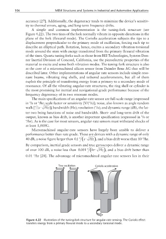
A simple and common implementation is the tuning-fork structure (see
Figure 4.22). The two tines of the fork normally vibrate in opposite directions in the
plane of the fork (flexural mode). The Coriolis acceleration subjects the tips to a
displacement perpendicular to the primary mode of oscillation, forcing each tip to
describe an elliptical path. Rotation, hence, excites a secondary vibration torsional
mode around the stem with energy transferred from the primary flexural vibration
of the tines. Quartz tuning forks such as those from BEI Technologies, Systron Don-
ner Inertial Division of Concord, California, use the piezoelectric properties of the
material to excite and sense both vibration modes. The tuning-fork structure is also
at the core of a micromachined silicon sensor from Daimler Benz AG that will be
described later. Other implementations of angular rate sensors include simple reso-
nant beams, vibrating ring shells, and tethered accelerometers, but all of them
exploit the principle of transferring energy from a primary to a secondary mode of
resonance. Of all the vibrating angular-rate structures, the ring shell or cylinder is
the most promising for inertial and navigational-grade performance because of the
frequency degeneracy of its two resonant modes.
The main specifications of an angular-rate sensor are full-scale range (expressed
in º/s or º/hr; scale factor or sensitivity [V/(º/s)]; noise, also known as angle random
walk [(° s ⋅ Hz )]; bandwidth (Hz); resolution (º/s); and dynamic range (dB), the lat-
ter two being functions of noise and bandwidth. Short- and long-term drift of the
output, known as bias drift, is another important specification (expressed in º/s or
º/hr). As is the case for most sensors, angular-rate sensors must withstand shocks of
at least 1,000G.
Micromachined angular-rate sensors have largely been unable to deliver a
performance better than rate grade. These are devices with a dynamic range of only
40 dB, a noise figure larger than 01. ° ( ⋅s Hz ), and a bias drift worse than 10 º/hr.
By comparison, inertial grade sensors and true gyroscopes deliver a dynamic range
of over 100 dB, a noise less than 0 001. ° ( ⋅hr Hz ), and a bias drift better than
0.01 º/hr [28]. The advantage of micromachined angular-rate sensors lies in their
Tine oscillation Coriolis acceleration
Figure 4.22 Illustration of the tuning-fork structure for angular-rate sensing. The Coriolis effect
transfers energy from a primary flexural mode to a secondary torsional mode.