
Page 125 - An Introduction to Microelectromechanical Systems Engineering
P. 125
104 MEM Structures and Systems in Industrial and Automotive Applications
of CMOS circuits next to the mechanical sensing element. The large available
capacitance makes the decision to integrate based purely on economics rather than
performance.
Angular Rate Sensors and Gyroscopes
Long before the advent of Loran and the satellite-based global positioning system,
the gyroscope was a critical navigational instrument used for maintaining a fixed
orientation with great accuracy, regardless of Earth rotation. Invented in the
nineteenth century, it consisted of a flywheel mounted in gimbal rings. The large
angular momentum of the flywheel counteracts externally applied torques and
keeps the orientation of the spin axis unaltered. The demonstration of the ring laser
gyroscope in 1963 displaced the mechanical gyroscope in many high-precision
applications, including aviation. Inertial navigation systems based on ring laser
gyroscopes are on board virtually all commercial aircraft. Gyroscopes capable of
precise measurement of rotation are very expensive instruments, costing many thou-
sands of dollars. An article published in 1984 by the IEEE reviews many of the basic
technologies for gyroscopes [24].
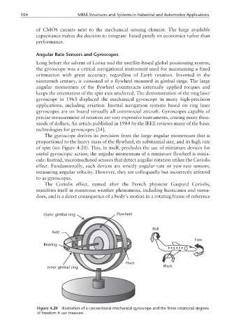
The gyroscope derives its precision from the large angular momentum that is
proportional to the heavy mass of the flywheel, its substantial size, and its high rate
of spin (see Figure 4.20). This, in itself, precludes the use of miniature devices for
useful gyroscopic action; the angular momentum of a miniature flywheel is minis-
cule. Instead, micromachined sensors that detect angular rotation utilize the Coriolis
effect. Fundamentally, such devices are strictly angular-rate or yaw-rate sensors,
measuring angular velocity. However, they are colloquially but incorrectly referred
to as gyroscopes.
The Coriolis effect, named after the French physicist Gaspard Coriolis,
manifests itself in numerous weather phenomena, including hurricanes and torna-
does, and is a direct consequence of a body’s motion in a rotating frame of reference
Outer gimbal ring Flywheel
Roll
Axle
Yaw
Bearing
Pivot
Inner gimbal ring Pitch
Figure 4.20 Illustration of a conventional mechanical gyroscope and the three rotational degrees
of freedom it can measure.