
Page 126 - An Introduction to Microelectromechanical Systems Engineering
P. 126
Sensors and Analysis Systems 105
(see Figure 4.21). To understand it, let us imagine an automobile driving from Seat-
tle, Washington (lat. 48º N), to Los Angeles, California (lat. 34º N). At the begin-
ning of its journey, the car in Seattle is actually moving eastward with the rotation of
Earth (the rotating frame of reference) at about 1120 km/h . At the end of its jour-
1
ney in Los Angeles, its eastward velocity is 1,385 km/h. As the car moves south
across latitudes, its eastward velocity must increase from 1,120 to 1,385 km/h; oth-
erwise, it will continuously slip and never reach its destination. The road—effec-
tively the rotating surface—imparts an eastward acceleration to maintain the
vehicle on its course. This is the Coriolis acceleration. In general, the Coriolis accel-
eration is the acceleration that must be applied in order to maintain the heading of a
body moving on a rotating surface [25].
All micromachined angular rate sensors have a vibrating element at their core—
this is the moving body. In a fixed frame of reference, a point on this element oscil-
lates with a velocity vector v. If the frame of reference begins to rotate at a rate Ω,
this point is then subject to a Coriolis force and a corresponding acceleration equal
to 2Ω× v [26]. The vector cross operation implies that the Coriolis acceleration
and the resulting displacement at that point are perpendicular to the oscillation.
This, in effect, sets up an energy transfer process from a primary mode of oscillation
into a secondary mode that can be measured. It is this excitation of a secondary
resonance mode that forms the basis of detection using the Coriolis effect. In beam
structures, these two frequencies are distinct with orthogonal displacements. But for
highly symmetrical elements, such as rings, cylinders, or disks, the resonant fre-
quency is degenerate, meaning there are two distinct modes of resonance sharing the
same oscillation frequency. This degeneracy causes the temporal excitation signal
(primary mode) to be in phase quadrature with the sense signal (secondary mode),
thus minimizing coupling between these two modes and improving sensitivity and
Ω
Ω
a c
v
z
y Coriolis acceleration:
x a= 2Ω×v
c
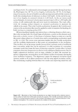
Figure 4.21 Illustration of the Coriolis acceleration on an object moving with a velocity vector v
on the surface of Earth from either pole towards the equator. The Coriolis acceleration deflects the
object in a counterclockwise manner in the northern hemisphere and a clockwise direction in the
southern hemisphere. The vector Ω represents the rotation of the planet.
1. The velocity at the equator is 1,670 km/h. The velocity at latitude 48º N is 1,670 km/h multiplied by cos 48º.