
Page 120 - An Introduction to Microelectromechanical Systems Engineering
P. 120
Sensors and Analysis Systems 99
the device, but it is very stiff in directions normal to the wafer, resulting in high
immunity to off-axis accelerations. Moreover, the outer frame acts as a stop mecha-
nism that protects the device in the event of excessive acceleration shocks. It takes
6,000G for the inertial mass to touch the frame, and the device can survive shocks in
excess of 10,000G. Open apertures reduce the weight of the inertial mass and com-
bine with the stiff hinge to provide a rather high resonant frequency of 28 kHz.
The fabrication process is somewhat unique with its utilization of {110} wafers
for the middle core. In this case, the {111} crystallographic planes are orthogonal to
the {110} surface of the wafer, which allows the formation of vertical trenches using
anisotropic wet etchants. The fabrication begins with boron implantation and diffu-
sion at 1,100ºC to form highly doped p-type piezoresistors. In order to obtain maxi-
mum sensitivity, the piezoresistors are aligned along a <111> direction. A silicon
oxide or silicon nitride layer masks the silicon in the form of the inertial mass and
hinge during the subsequent anisotropic etch in EDP. The inertial mass is bounded
by vertical {111} planes, giving it the shape of a parallelogram whose inside angle is
70.5º (see Chapter 3). Subsequent fabrication steps provide for the deposition and
patterning of aluminum electrical contacts and bond pads. Shallow recesses are
incorporated in the base and lid substrates before the three-wafer stack is bonded
together using low-melting-point glass as the adhesive.
Capacitive Bulk Micromachined Accelerometer
Many companies offer capacitive bulk-micromachined accelerometers. The next
example describes the SCA series from VTI Technologies of Vantaa, Finland. The
sensor consists of a stack of three bonded silicon wafers, with the hinge spring and
inertial mass incorporated in the middle wafer. The inertial mass forms a moveable
inner electrode of a variable differential capacitor circuit. The two outer wafers are
identical and are simply the fixed electrodes of the two capacitors (see Figure 4.16).
Holes through the inertial mass reduce the damping effect from air trapped in
the enclosed cavity, increasing the operating bandwidth of the sensor. Unlike other
designs, the contacts to the electrodes are on the side of the die and thus must be
defined after the wafer is diced into individual sensor parts. The SCA series of sen-
sors is available in a measuring range from ±0.5G to ±12G. Electronic circuits sense
changes in capacitance, then convert them into an output voltage between 0 and 5V.
The rated bandwidth is up to 400 Hz for the ±12G accelerometer, the cross-axis
sensitivity is less than 5% of output, and the shock immunity is 20,000G.
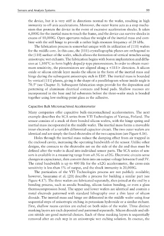
The particulars of the VTI Technologies process are not publicly available;
however, Sasayama et al. [20] describe a process for building a similar part (see
Figure 4.17). The three wafers are fabricated separately, then joined at the end by a
bonding process, such as anodic bonding, silicon fusion bonding, or even a glass
thermocompression bond. The upper and lower wafers are identical and contain a
metal electrode patterned with standard lithography over a thin layer of silicon
dioxide. The inertial mass and hinge are delineated in the middle wafer using four
sequential steps of anisotropic etching in potassium hydroxide or a similar etchant.
First, shallow recess cavities are etched on both sides of the wafer. Three distinct
masking layers are each deposited and patterned separately. Silicon dioxide and sili-
con nitride are good material choices. Each of these masking layers is sequentially
removed after an etch step in an anisotropic wet etching solution. In essence, the