
Page 118 - An Introduction to Microelectromechanical Systems Engineering
P. 118
Sensors and Analysis Systems 97
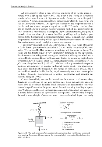
All accelerometers share a basic structure consisting of an inertial mass sus-
pended from a spring (see Figure 4.14). They differ in the sensing of the relative
position of the inertial mass as it displaces under the effect of an externally applied
acceleration. A common sensing method is capacitive, in which the mass forms one
side of a two-plate capacitor. This approach requires the use of special electronic
circuits to detect minute changes in capacitance (<10 −15 F) and to translate them
into an amplified output voltage. Another common method uses piezoresistors to
sense the internal stress induced in the spring. In yet a different method, the spring is
piezoelectric or contains a piezoelectric thin film, providing a voltage in direct pro-
portion to the displacement. In some rare instances, such as in operation at elevated
temperatures, position sensing with an optical fiber becomes necessary. The focus of
this section is on capacitive and piezoresistive accelerometers.
The primary specifications of an accelerometer are full-scale range, often given
in G, the Earth’s gravitational acceleration (1 G = 9.81 m/s ), sensitivity (V/G), reso-
2
lution (G), bandwidth (Hz), cross-axis sensitivity, and immunity to shock. The
range and bandwidth required vary significantly depending on the application.
Accelerometers for airbag crash sensing are rated for a full range of ±50G and a
bandwidth of about one kilohertz. By contrast, devices for measuring engine knock
or vibration have a range of about 1G, but must resolve small accelerations (<100
µG) over a large bandwidth (>10 kHz). Modern cardiac pacemakers incorporate
multiaxis accelerometers to monitor the level of human activity, and correspond-
ingly adjust the stimulation frequency. The ratings on such sensors are ±2G and a
bandwidth of less than 50 Hz, but they require extremely low power consumption
for battery longevity. Accelerometers for military applications such as fuzing can
exceed a rating of 1,000G.
Cross-axis sensitivity assesses the immunity of the sensor to accelerations along
directions perpendicular to the main sensing axis. Cross-axis rejection ratios in
excess of 40 dB are always desirable. Shock immunity is an important but somewhat
subjective specification for the protection of the devices during handling or opera-
tion. While one would expect the specification quantified in units of acceleration, it
is instead defined in terms of a peculiar but more practical test involving dropping
the device from a height of one meter over concrete—the shock impact can easily
Resonant frequency:
1 k
f =
r
2π M
k
Spring ( )
Noise equivalent acceleration:
8πKTf B
δ= F/k a = B r ; B < f
Inertial noise QM r
mass ( )
M
M K = Boltzmann constant
B
T = Temperature
B = Bandwidth
⋅
F = M a Q = Quality factor
Figure 4.14 The basic structure of an accelerometer, consisting of an inertial mass suspended
from a spring. The resonant frequency and the noise-equivalent acceleration (due to Brownian
noise) are given.