
Page 249 - An Introduction to Microelectromechanical Systems Engineering
P. 249
228 Packaging and Reliability Considerations for MEMS
(ohmic) contacts to aluminum bond pads on the die and to the package leads (termi-
nals). Bonding gold wires tends to be easier than bonding aluminum wires.
Thermosonic gold bonding is a well-established technique in the integrated cir-
cuit industry, simultaneously combining the application of heat, pressure, and ultra-
sonic energy to the bond area. Ultrasound causes the wire to vibrate, producing
localized frictional heating to aid in the bonding process. Typically, the gold wire
forms a ball bond to the aluminum bond pad on the die and a stitch bond to the
package lead. The “ball bond” designation follows after the spherical shape of the
wire end as it bonds to the aluminum. The stitch bond, in contrast, is a wedge-like
connection as the wire is pressed into contact with the package lead (typically gold
or silver plated). The temperature of the substrate is usually near 150ºC, below the
threshold of the production of gold-aluminum intermetallic compounds that cause
bonds to be brittle. One of these compounds (Au Al ) is known as purple plague
5 12
and is responsible for the formation of voids—the Kirkendall voids—by the diffu-
sion of aluminum into gold. Thermosonic gold bonding can be automated using
equipment commercially available from companies such as Kulicke and Soffa Indus-
tries, Inc., of Willow Grove, Pennsylvania.
Bonding aluminum wires to aluminum bond pads is also achieved with ultra-
sonic energy but without heating the substrate. In this case, a stitch bond works bet-
ter than a ball bond, but the process tends to be slow. This makes bonding aluminum
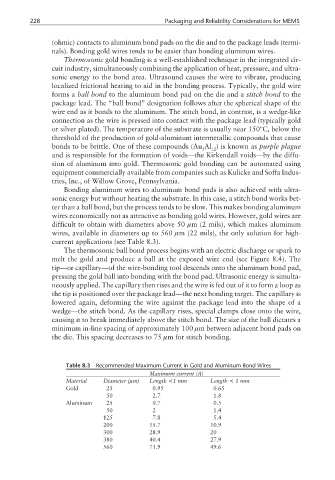
wires economically not as attractive as bonding gold wires. However, gold wires are
difficult to obtain with diameters above 50 µm (2 mils), which makes aluminum
wires, available in diameters up to 560 µm (22 mils), the only solution for high-
current applications (see Table 8.3).
The thermosonic ball bond process begins with an electric discharge or spark to
melt the gold and produce a ball at the exposed wire end (see Figure 8.4). The
tip—or capillary—of the wire-bonding tool descends onto the aluminum bond pad,
pressing the gold ball into bonding with the bond pad. Ultrasonic energy is simulta-
neously applied. The capillary then rises and the wire is fed out of it to form a loop as
the tip is positioned over the package lead—the next bonding target. The capillary is
lowered again, deforming the wire against the package lead into the shape of a
wedge—the stitch bond. As the capillary rises, special clamps close onto the wire,
causing it to break immediately above the stitch bond. The size of the ball dictates a
minimum in-line spacing of approximately 100 µm between adjacent bond pads on
the die. This spacing decreases to 75 µm for stitch bonding.
Table 8.3 Recommended Maximum Current in Gold and Aluminum Bond Wires
Maximum current (A)
Material Diameter (µm) Length <1 mm Length < 1mm
Gold 025 00.95 00.65
050 02.7 01.8
Aluminum 025 00.7 00.5
050 02 01.4
125 07.8 05.4
200 15.7 10.9
300 28.9 20
380 40.4 27.9
560 71.9 49.6