
Page 252 - An Introduction to Microelectromechanical Systems Engineering
P. 252
Wiring and Interconnects 231
Microfluidic Interconnects
All advances in electrical interconnect technology derive from the packaging
requirements of the integrated circuit industry, but that is not the case for fluidic
interconnects. These are required to package microfluidic devices such as micro-
pumps and microvalves. No standards exist simply because the field remains in its
infancy and few microfluidic devices are commercially available. Sadly, most micro-
fluidic interconnect schemes remain at the level of manually inserting a capillary
into a silicon cavity or via-hole and sealing the assembly with silicone or epoxy (see,
for example, the PCR thermal cycler in Chapter 6). These are suitable methods for
laboratory experimentation but will not meet the requirements of automated manu-
facturing (see Figure 8.6).
Future fluid packaging schemes amenable to high-volume manufacturing
would have to rely on simplified fluid interconnects. For example, fluid ports in a
silicon die could be aligned directly to ports in a ceramic or metal manifold. The sili-
con die can be attached by any of the die-attach methods described earlier. Under
such a scheme, it becomes possible to envisage systems with fluid connectivity on
one side of the die and electrical connectivity on the opposite side. This would
enhance long-term reliability by separating fluid flow from electrical wiring.
Researchers at Abbott Laboratories of Abbott Park, Illinois, demonstrated a
hybrid packaging approach incorporating a complex manifold in acrylic (e.g., Plexi-
glas™) [13]. These are large boards, many centimeters in size, with multiple levels of
channels and access vias, all made in plastic. The channels are formed by laminating
and bonding layers of thermoplastics into which trenches had been preformed. The
plastic board becomes equivalent to a fluid printed-circuit board onto which surface
fluid components are attached and wired. These components need not necessarily be
micromachined. For example, the board could hold a silicon pressure or flow sensor
in proximity of a miniature solenoid valve. Much of the technology for fluid inter-
connects remains under development. New markets and applications will undoubt-
edly drive engineers to contrive innovative but economically justifiable solutions.
µ
200 m
(a) (b)
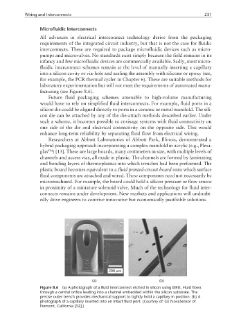
Figure 8.6 (a) A photograph of a fluid interconnect etched in silicon using DRIE. Fluid flows
through a central orifice leading into a channel embedded within the silicon substrate. The
precise outer trench provides mechanical support to tightly hold a capillary in position. (b) A
photograph of a capillary inserted into an intact fluid port. (Courtesy of: GE NovaSensor of
Fremont, California [12].)