
Page 253 - An Introduction to Microelectromechanical Systems Engineering
P. 253
232 Packaging and Reliability Considerations for MEMS
Optical Interconnects
Optical interconnecting is generally understood as the active field of research that
aims to develop very fast chip-to-chip transmission rates for high-speed computa-
tion. For the packaging of MEMS components in photonic applications, optical
interconnects are simpler in nature, generally entailing coupling light in and out of
an optical fiber without a noticeable loss (typically <0.1 dB). The laser and optoe-
lectronic industry makes extensive use of fiber interconnects for the packaging and
manufacture of their products. Companies packaging optical MEMS components
have largely borrowed these established packaging designs and methods for their
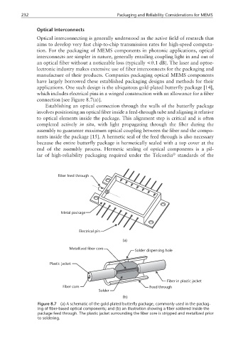
applications. One such design is the ubiquitous gold-plated butterfly package [14],
which includes electrical pins in a winged construction with an allowance for a fiber
connection [see Figure 8.7(a)].
Establishing an optical connection through the walls of the butterfly package
involves positioning an optical fiber inside a feed-through tube and aligning it relative
to optical elements inside the package. This alignment step is critical and is often
completed actively in situ, with light propagating through the fiber during the
assembly to guarantee maximum optical coupling between the fiber and the compo-
nents inside the package [15]. A hermetic seal of the feed through is also necessary
because the entire butterfly package is hermetically sealed with a top cover at the
end of the assembly process. Hermetic sealing of optical components is a pil-
®
lar of high-reliability packaging required under the Telcordia standards of the
Fiber feed through
Metal package
Electrical pin
(a)
Metallized fiber core
Solder dispensing hole
Plastic jacket
Fiber in plastic jacket
Fiber core Feed through
Solder
(b)
Figure 8.7 (a) A schematic of the gold-plated butterfly package, commonly used in the packag-
ing of fiber-based optical components; and (b) an illustration showing a fiber soldered inside the
package feed through. The plastic jacket surrounding the fiber core is stripped and metallized prior
to soldering.