
Page 160 - Analog and Digital Filter Design
P. 160
157
Highpass Filters
where ois the pole position on the negative real axis of the S-plane. As the cut-
off frequency increases, the highpass pole o///, moves further from the origin.
The denormalization process requires the value of to be multiplied by ZnF,.
hence the normalized value of R'1 must be divided by the frequency ccalinp
factor. Thus, for a given capacitor value. the resistor ralue must decrease to raise
the cutoff frequency.
Does this make sense'? Well. intuitively. you may be able to see that by reducing
the value of R the potential at the node between Cand R will be lower at a ~iven
frequency. Increasing this frequency lowers the capacitor's reactance and
restores the potential to what it was at the original frequency. In other words.
to maintain a certain potential (for example. the 3dB point of 0.7071 volts) at
ii higher frequency requires a reduction in the value of R.
Sallen and Key Highpass Filter
The Sallen and Key filter produces a second-order all-pole response and is
;I simple active highpass design. It can be used for Bessel. Butterworth. or
Chebyshev responses. Cascading second-order sections can produce high-order
filters. Odd-order filters can be produced by using a series of second-order sec-
tions and then adding a first-order section at the end.
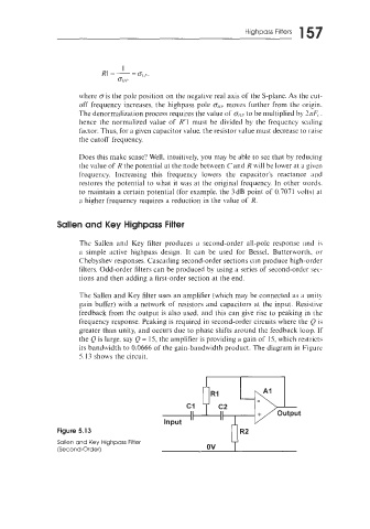
The Sallen and Key filter uses an amplifier (which may be connected as a unity
gain buffer) with a network of resistors and capacitors at the input. Resistive
feedback from the output is also used. and this can give rise to peaking in the
frequency response. Peaking is required in second-order circuits where the Q is
greater than unity, and occurs due to phase shifts around the feedback loop. If
the Q is large, say Q = 15, the amplifier is providing a gain of 15, which restricts
its bandwidth to 0.0666 of the gain-bandwidth product. The diagram in Figure
5.13 shows the circuit.
+ output
c1
Input
Figure 5.13 R2
Sallen and Key Highpass Filter ov
(Second-Order)