
Page 165 - Analog and Digital Filter Design
P. 165
1 62 Analog and Digital Filter Design
The equations for this filter require the use of normalized highpass pole loca-
tions. They allow the arbitrary choice of capacitor, C.
1
Rl=R4=-
2oHPc
The value of R6 determines the gain: R6 = KR, where K = gain. The value of
R' is arbitrary, but a typical value could be 10 kR.
An odd-order filter is made from second-order sections connected in series, fol-
lowed by a first-order section. The second-order sections are all as just described,
requiring four op-amps for each pole pair. The first-order section is usually
added at the end of the second-order sections, and comprises a CR network
followed by an op-amp.
Cauer and Inverse Chebyshev Active Filters
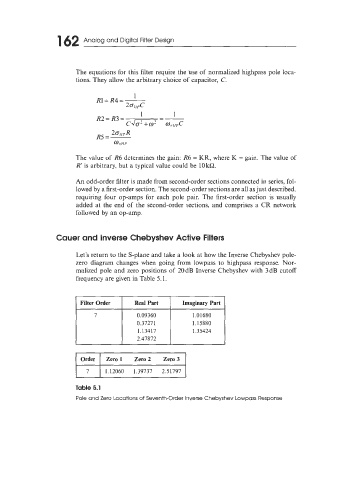
Let's return to the S-plane and take a look at how the Inverse Chebyshev pole-
zero diagram changes when going from iowpass to highpass response. Nor-
malized pole and zero positions of 20dB Inverse Chebyshev with 3dB cutoff
frequency are given in Table 5.1.
I Filter Order I Real Part I Imaginary Part
7 0.09360 1.01680
0.37271 1. I5880
1.13417 1.35424
2.47872
Order Zero 1 Zero 2 Zero 3
7 1.12060 1.39737 2.51797