
Page 166 - Analog and Digital Filter Design
P. 166
163
Highpass Filters
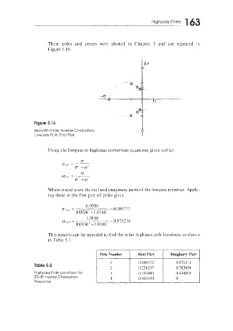
These poles and zeroes were plotted in Chapter 3 and are repeated in
Figure 5.16.
Figure 5.16
Seventh-Order Inverse Chebyshev
Lowpass Pole Zero Plot
LJsing the lowpass to highpass conversion equations given earlier:
Where (T and ware the real and imaginary parts of the lowpass response. Apply-
ing these to the first pair of poles gives:
0.0936
Dl 111' = = 0.089772
0.0936' +I ,0168'
1.0168
=
~ll//~ = 0.979 14
0.0936' +l.Ol68'
This process can be repeated to find the other highpass pole locations, as sho\in
in Table 5.2.
Pole Number Real Part Imaginary Part
I 0.089772 0.975214
Table 5.2
2 0.251537 0.782059
Highpass Pole Locations for 3 0.363480 0.4340 10
20dB Inverse Chebyshev 4 0.403434 0
Response