
Page 171 - Analog and Digital Filter Design
P. 171
1 68 Analog and Digital Filter Design
Input - shunt "L"
f
p::
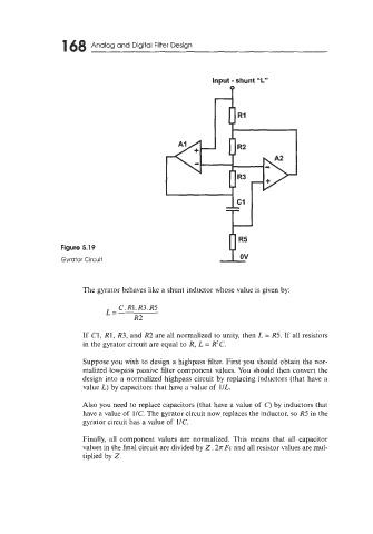
Figure 5.19
Gyrator Circuit
The gyrator behaves like a shunt inductor whose value is given by:
C. R1. R3. R5
L=
R2
If C1, R1, R3, and R2 are all normalized to unity, then L = R5. If all resistors
in the gyrator circuit are equal to R, L = R?C.
Suppose you wish to design a highpass filter. First you should obtain the nor-
malized lowpass passive filter component values. You should then convert the
design into a normalized highpass circuit by replacing inductors (that have a
value L) by capacitors that have a value of 1IL.
Also you need to replace capacitors (that have a value of C) by inductors that
have a value of UC. The gyrator circuit now replaces the inductor, so R5 in the
gyrator circuit has a value of 1/C.
Finally, all component values are normalized. This means that all capacitor
values in the final circuit are divided by Z .2n Fc and all resistor values are mul-
tiplied by Z.