
Page 172 - Analog and Digital Filter Design
P. 172
169
Highpass Filters
For example, suppose you wish to design a third-order highpass filter using a
gyrator. The filter should have a passband cutoff frequency of 10 kHz with input
and output impedance of 600R.
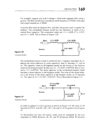
A passive filter must be designed first, and then the gyrator used to replace the
inductor. The normalized lowpass model has two inductors in series with a
central shunt capacitor. The component values are: L1 = 1.4328; C'2 = 1.5937:
and L3 = 1.4328. This is shown in Figure 5.20.
Rs=l L1=1.4328 L3=1.4328
P
Source RL=I
Figure 5.20
Lowpass Model
The normalized lowpass model is converted into a highpass equivalent by re-
placing the series inductors by series capacitors; thus LI becomes C1, and so
on. The capacitor values in the highpass model are the inverse of the inductor
values in the lowpass model. In this case, C1 = U1.4328 = 0.697934. Due to sym-
metry, C3 = 0.697934. The shunt capacitor in the normalized lowpass model
becomes a shunt inductor in the highpass model. The value of the shunt induc-
tor is the inverse of the shunt capacitor in the lowpass model, so C2 becomes
L2. The value of L2 = 1/1.5937 = 0.627471. This is illustrated in Figure 5.21.
C1=1/1.4328
Source
L2=1/1.5937 RL=I
Figure 5.21 =0.6275
Highpass Model
In order to replace L2 with a gyrator, as shown in Figure 5.19, the value of R5
becomes 0.627471, with R1 = R2 = R3 = 1 R, and C2 of the gyrator circuit equals
1 E
To denormalize the filter, all resistor values must be multiplied by the load
impedance of 600R. Resistors, RI, R?. and R3 all become 600R. R5 becomes