
Page 177 - Analog and Digital Filter Design
P. 177
1 74 Analog and Digital Filter Design
bandpass filter bandwidth will be the same as the lowpass filter from which it
was derived. Figure 6.1 illustrates this.
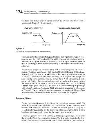
LOWPASS PROTOTYPE TRANSFORMED BANDPASS
I Frequency I Frequency
Figure 6.1
Lowpass to Bandpass Response Transformation
The relationship between the bandpass filter and its lowpass prototype does not
only apply to the -3 dB bandwidth. The width of the skirt in the bandpass filter
response, at any given amount of attenuation, will be equal to the width of the
skirt in the lowpass filter response frequency at which the same attenuation is
achieved.
For example, suppose a bandpass filter with a center frequency of 10 kHz is
desired. This filter must have a -3dB bandwidth of 6.8 kHz and 40dB attenua-
tion at Fc k 10 kHz, that is, the width of the skirt response at 40dB attenuation
is 20kHz. The bandpass filter must be based on a lowpass filter design that
produces the same response. That is, it must have 40dB attenuation at a fre-
quency of 20 kHz. The normalized stopband-to-passband frequency ratio of
the lowpass filter is the same as that of the bandpass filter: 20 kHz divided by
6.8 kHz, which gives a ratio of 2.94. Thus, in a normalized lowpass prototype
with a 1 radls passband frequency, 40dB attenuation is required at a frequency
of 2.94radls. The normalized lowpass attenuation curves given in Chapter 2 can
be examined to find the filter order required to achieve this response.
Passive Filters
Passive bandpass filters are derived from the normalized lowpass model. The
model is normalized for a passband that extends from DC to 1 rad/s and is ter-
minated with a 1 R load resistance. The first process that you must carry out is
to scale the lowpass model for the desired cutoff frequency, transform it into a
bandpass filter, and, finally, scale for the correct load impedance.
The design process starts with identifying the lowpass prototype. This may be
Butterworth, Chebyshev, or another design. The filter order must also be deter-
mined. Starting with the specification given in the introduction, you need a filter