Page 178 - Analog and Digital Filter Design
P. 178

Bandpass Filters   175


                       with a 6.8 kHz 3dB bandwidth and with 40dB attenuation at flOkHz. In addi-
                       tion, let the filter have a center frequency, Fo, of  198 kHz. Design a Butterworth
                       bandpass filter that achieves this specification.

                       The stopband-to-passband  ratio  is 20/6.8 = 2.94, as explained  in  the previous
                       example. Referring to the attenuation  versus frequency curves for Butterworth
                       filters, you can see that a fifth-order filter will provide the required performance.
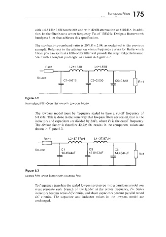
                       Start with a lowpass prototype, as shown in  Figure 6.2.


                             Rs= 1          L2=1.618       L4=1.618


                        Source
                                     --               --             --               R=l
                                     --
                                                                     --
                                                      --
                                        C1=0.618
                                                         C3=2.000
                                                                        C5=0.618
                 Figure 6.2
                 Normalized Fifth-Order Butterworth LowDass Model


                       The  lowpass  model  must  be  frequency  scaled  to  have  a  cutoff  frequency  of
                       6.8 kHz. This is done in the same way that lowpass filters are scaled, that is. the
                       inductors and capacitors are divided by 31rFc, where Fc is the cutoff  frequency.
                       The divisor  factor is  therefore 42,725.66; results in  the component values are
                       shown in Figure 6.3.

                            Rs= 1          L2=37.87uH


                                                        c3
                       Source          14.4644~         -               c5      F      R=l
                                    t                   -            --
                                                        46.81 03uF
                                               F
                                                                     --
                                                                        14.4644~

                 Figure 6.3
                 Scaled Fifth-Order Butterworth Lowpass Filter

                       To frequency translate the scaled lowpass prototype into a bandpass model yo~~
                       must  resonate  each  branch  of  the  ladder  at  the  center  frequency, Fo.  Series
                       inductors become series LC circuits, and shunt capacitors become parallel tuned
                       LC  circuits.  The  capacitor  and  inductor  values  in  the  lowpass  model  are
                       unchanged.
   173   174   175   176   177   178   179   180   181   182   183