
Page 179 - Analog and Digital Filter Design
P. 179
1 76 Analog and Digital Filter Design
1
Remember that for a tuned circuit at resonance, Fo = ~ The inductor
2nm.
and capacitor values can be found by manipulating this equation. Hence the
1
inductor required to tune the lowpass capacitor becomes LBp =
~~'FO~C,,~'
and the capacitor required to tune the lowpass inductor becomes
1
CBP =
Fo'
4~' L,, '
For the bandpass filter tuned to 198 kHz, the frequency translating factor is
4dFo' = 1.547712 x 10". Using this information the bandpass circuit compo-
nent values are given in Table 6.1.
Lowpass Bandpass
Component Lowpass Value Component Bandpass Value
c1 14.4644 x L1 44.669 x 10-~
L2 37.87 x c2 17.0614 x
c3 46.8103 x L3 13.8028 x
L4 37.87 x c4 17.0614 x lo-'
c5 14.4644 x L5 44.669 x 10-~
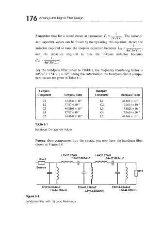
Putting these components into the circuit, you now have the bandpass filter
shown in Figure 6.4.
II II
-- -- R=l
--
--