
Page 184 - Analog and Digital Filter Design
P. 184
Bandpass Filters 1
The zero-producing series branch, L2 and C2, is a parallel resonant circuit. En
the bandpass filter derived from this prototype two zeroes need to be produced.
Therefore it is necessary to replace L2 and C, with two parallel resonant circuits
that are connected in series. In the transformed circuit, one resonant circuit com-
prises L,, and C,, the other Lh and C,,. The resonant circuit comprising L,, and
CLl gives a zero above the passband; the resonant circuit comprising L/, and C,
gives a zero below the passband.
The zero frequencies are given by wmd = fi and ab = 1/a where p is
given by:
1 I 1 1
From this the transformed circuit pairs can be found:
1
L,, =
c2 (p + 1) = 0.75048
but L,, = PL,, = 7.53896
1 1
C,, = - 0.13247 and C/, = - = 1.33248.
=
Lh L /I
These component values must then be normalized. Multiply inductor values by
R and divide them by 27tl7,; divide capacitor values by 2nER. Notice that only
the value of C, is required in these equations. in addition to p. This also applies
to equations that will be given later, which convert the lowpass prototype directly
into a bandpass design.
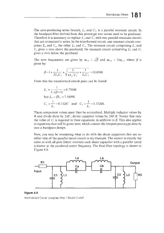
Now, you may be wondering what to do with the shunt capacitors that are on
either side of the parallel tuned circuit in my example. The answer is exactly the
same as with all-pole filters: resonate each shunt capacitor with a parallel tuned
inductor at the passband center frequency. The final filter topology is shown in
Figure 6.8.
La Lb
Figure 6.8
Normalized Cauer Lowpass Filter. 1 Rad/s Cutoff