
Page 187 - Analog and Digital Filter Design
P. 187
1 84 Analog and Digital Filter Design
response, with poles on a unit circle at -0.9239 t j0.3827 and -0.3827 f j0.9239.
Suppose the filter is required to have a passband between 9 radls and 11 radls
(BW= 2, this is for illustration only and not intended to be a practical value).
This gives B W= 2, wo = 9.95rad/s, and QBp = 4.975. Notice that the geometric
center frequency (9.95radh) is not the same as the arithmetic center frequency
(10rad/s). Taking one pole from the first pair: s = -0.9239 + j0.3827, Q= 0.9239,
and w = 0.3827.
The two bandpass poles produced from this are found from the following
equations:
d
~?~=-=0.18571
QBP
w
J = - 0.076925
=
QBP
n = tn2 + J' + 4 = 4.0404056
W=Qm+JF = 1.039375
1
-
171-
f;l
The frequencies are fRI = - 9.57306 and fR2 = Wf;, 10.34178.
=
=
W
The second pair of poles can be found in a similar way. Due to symmetry
Q = 0.3827 and w = 0.9239:
Q
t?l= - 0.076925
=
QBP
w
J = - 0.18571
=
QBP
n = in2 + J' + 4 = 4.0404056
Q = ,/n+Jn'-lbni = 13.0556778
8ni'
W = Qin + 4- = 1.09723
fn
The frequencies are fRI = - = 9.068286 and fR: = Wfo = 10.917444.
W
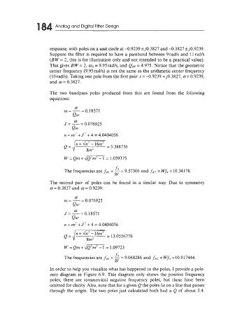
In order to help you visualize what has happened to the poles, I provide a pole-
zero diagram in Figure 6.9. This diagram only shows the positive frequency
poles; there are symmetrical negative frequency poles, but these have been
omitted for clarity. Also, note that for a given Q the poles lie on a line that passes
through the origin. The two poles just calculated both had a Q of about 5.4.