
Page 188 - Analog and Digital Filter Design
P. 188
Bandpass Filters 18
The other poles had a Q of about 13, but are further from the bandpass filter’s
center frequency, Fc. Remember that the Q of a pole is given by the equation:
lFG7
20
The Q of a bandpass pole is approximately ~ 2woQLp where QLP is the normal-
B FV
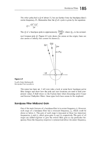
ized lowpass pole Q. Figure 6.9 only shows the zeroes at the origin; there are
also zeroes at infinity that cannot be shown (!).
Figure 6.9
Fourth-Order Butterworth
Bandpass Poie Locations
The scene has been set. I will now take a look at some basic bandpass active
filter designs and show how the pole and zero locations are used to find com-
ponent values. I shall return to the S-plane later when discussing active Cauer
and Inverse Chebyshev filters: these types both have zeroes in the stopband.
Bandpass Filter Midband Gain
One of the main features of a bandpass filter is its center frequency,f,. However,
each stage of a bandpass filter has a resonant frequency, fR, which could be
above or belowh,. The gain of each stage is measured at these two important
frequencies, fo and .fR, which gives gain Go and G, respectively. The gain of all
stages are added together to give the overall filter gain at any particular fre-
quency. Since the frequency response is symmetrical about the center frequency,