
Page 174 - Analog and Digital Filter Design
P. 174
Highpass Filters 1 7 1
c1 c3
18.5133nF 18.5133nF
c2=
R5=752
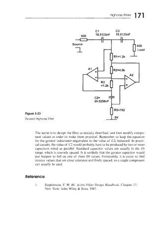
Figure 5.23
Revised Highpass Filter
The secret is to design the filter as initially described. and then modify compo-
nent values in order to make them PrdCtiCal. Remember to keep the equation
for the gyrator inductance (equivalent to the value of L2) balanced. In practi-
cal circuits. the value of C2 would probably have to be produced by two or more
capacitors wired in parallel. Standard capacitor values are usually in the E6
range, which is coarsely spaced. It is unlikely that the gyrator capacitor ~vould
just happen to fall on one of these E6 values. Fortunately, it is easier to find
resistor values that are close tolerance and finely spaced, so a single component
can usually be used.
Reference
1. Stephenson, E W. RC Active Filter Design Haridbook. Chapter 13.
New York: John Wiley & Sons. 1985.