
Page 161 - Analog and Digital Filter Design
P. 161
1 58 Analog and Digital Filter Design
Using Lowpass Pole to Find Component Values
By letting C1 and C2 equal 1F in the normalized design, the values of R1 and
R2 can easily be calculated from the lowpass pole locations.
7
Rl=-- W,LP - oLp and R2 = 2unLPQLP OLP- + WLP-
=
~QLP CLP
Lowpass pole positions have been used because they are readily available in
tables. Thus it is not necessary to convert to highpass pole positions first. Note
that in the case of Butterworth filters, a,,= 1 (for highpass and lowpass).
For example, given that the locations of the first pair of lowpass poles of a
Buttenvorth fourth-order filter is 0.9239 k j0.3827. A Sallen and Key filter
section, having the same pole locations, has resistor values R1 = 0.9239 and R2
= 1.0824. As previously stated, to use the simplified equations, the normalized
highpass has capacitor values of 1 Farad.
The numbering of resistors in the next filter section follows the number sequence
and are labeled R3 and R4. The value of R3 and R4 can be calculated from the
same equations that were used to find R1 and R2. Substitute R3 for R1 and R4
for R2. With poles at 0.3827 f j0.9239 this filter section has resistor values of
R3 = 0.3827 and R4 = 2.613.
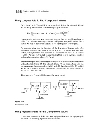
The diagram in Figure 5.14 illustrates the whole circuit.
E-""
Figure 5.14
Fourth-Order Filter
Using Highpass Poles to Find Component Values
If you want to design a Sallen and Key highpass filter from its highpass pole
positions, the following equations should be used: