
Page 156 - Analog and Digital Filter Design
P. 156
Highpass Filters 153
in the highpass design. This also applies to the component values in the paral-
lel tuned circuit. The parallel tuned arm between the shunt capacitors of the
lowpass prototype is also present in the highpass design. However, in the high-
pass circuit, the value of the inductor is derived from the capacitor value in the
prototype, and the value of the capacitor is derived from the inductor value in
the prototype. The value of the highpass component is the inverse of the lowpass
design. This uses the same equations as before.
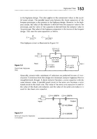
This highpass circuit is illustrated in Figure 5.8
C2'= 1 lL2
=0.98298
output
R2= 1
Figure 5.8 L3'=1/C3
=1.05574
Third-Order Highpass
Filter
Generally, circuits with a minimum of inductors are preferred for ease of man-
ufacture. Conversion from this design into minimum inductor highpass filters is
straightforward, though. A shunt inductor becomes a series capacitor with the
same element value. A parallel tuned circuit in the series arm becomes a series
tuned circuit in the shunt arm. The value of the series arm capacitor is used for
the value of the shunt arm inductor, and the value of the series arm inductor is
used for the shunt arm capacitor.
RI=I
-TI output
C1'=1.05574 C3'=1.05574
Input
C2'=8.29944
R2= 1
Figure 5.9 L2'=0.98298
Minimum Inductor Highpass
Conversion