
Page 151 - Analog and Digital Filter Design
P. 151
1 48 Analog and Digital Filter Design
capacitance value that it replaced. Also, the capacitance value will be the recip-
rocal of the inductance value that it replaced. The LC network will then res-
onate at the reciprocal of its lowpass frequency.
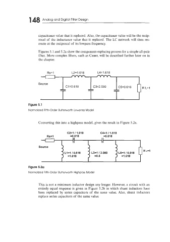
Figures 5.1 and 5.2a show the component-replacing process for a simple all-pole
filter. More complex filters, such as Cauer, will be described further later on in
the chapter.
Rs= 1 L2=1.618 L4= 1.6 1 8
Figure 5.1
Normalized Fifth-Order Butterworth Low~ass Model
Converting this into a highpass model, gives the result in Figure 5.2a.
C2=1 11.618 C4=1 11.618
Rs=l =0.618 =0.618
I II II
Source
R L=I
Ll=l 10.618 L3=1 12.000 L5=1 10.618
=1.618 =os =1.618
Figure 5.2a
Normalized Fifth-Order Butterworth Highpass Model
This is not a minimum inductor design any longer. However, a circuit with an
entirely equal response is given in Figure 5.2b in which shunt inductors have
been replaced by series capacitors of the same value. Also, shunt inductors
replace series capacitors of the same value.