
Page 153 - Analog and Digital Filter Design
P. 153
50 Analog and Digital Filter Design
tance values by 27r times the cutoff frequency (in Hertz). Inductance values can
be reduced because their impedance is proportional to frequency. To maintain
the same impedance at a higher frequency requires less inductance. Capacitor
values can also be reduced because a capacitor’s impedance is inversely pro-
portional to the frequency, to have the same impedance at a higher frequency
requires less capacitance.
Since the normalized model has a 1 rad/s cutoff frequency, the scaling factor is
2nF, to convert the frequency into Hertz. Let’s design a highpass filter with a
100 kHz cutoff frequency and 600R termination. The frequency scaling factor
is 27r. 100.10’ = 628.32. lo3. In other words, the cutoff frequency required is
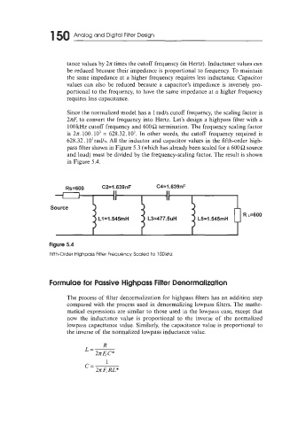
628.32.103rad/s. All the. inductor and capacitor values in the fifth-order high-
pass filter shown in Figure 5.3 (which has already been scaled for a 600R source
and load) must be divided by the frequency-scaling factor. The result is shown
in Figure 5.4.
Rs=600 CZ=l.639nF C431.639nF
1 II II
II
Source
R ~=600
L1=1.545mH L3=477.5uH L5=1.545mH
Figure 5.4
Fifth-Order Highpass Filter Frequency Scaled to 100 khz
Formulae for Passive Highpass Filter Denormalization
The process of filter denormalization for highpass filters has an addition step
compared with the process used in denormalizing lowpass filters. The mathe-
matical expressions are similar to those used in the lowpass case, except that
now the inductance value is proportional to the inverse of the normalized
lowpass capacitance value. Similarly, the capacitance value is proportional to
the inverse of the normalized lowpass inductance value.
R
L=-
27rF,c*
1
C=
2x6 RL*