
Page 154 - Analog and Digital Filter Design
P. 154
Highpass Filters 151
L* and C* are the normalized lowpass component values. L and C are the final
values after scaling. Usually the design would be scaled for impedance and fre-
quency in one step. using the given formulae.
Here is a simple example using the formulae. Design a third-order highpass filter
having a 0.25dB Chebyshev response. a 2OkHz cutoff frequency. infinite (open
circuit) load, and source impedance of 150R. Note that the source impedance
is quoted, but the load is infinite. Referring to Tables 2.16 to 2.20 in Chapter 2
for Chebyshev passive filters, you will notice that they are for filters having
a zero or infinite source impedance. The normalized values of a 0.15dB
Chebyshev lowpass model with infinite load impedance can be found by revers-
ing the order of the elements.
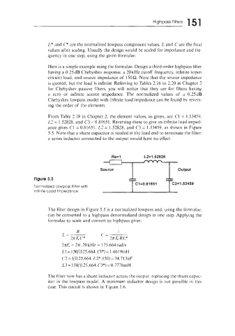
From Table 2.18 in Chapter 2. the element values, as given, are C1 = 1.53459.
L2 = 1.52828. and C3 = 0.81651. Reversing these to give an infinite load imped-
ance gives C1 = 0.81651. LZ = 1.52828, and C3 = 1.53459, as shown in Figure
5.5. Note that a shunt capacitor is needed at the load end to terminate the filter:
a series inductor connected to the output would have no effect.
Rs=l L2=1.52828
Source output
Figure 5.5
Normalized Lowpass Filter with
Infinite Load Impedance
The filter design in Figure 5.5 is a normalized lowpass and, using the formulae.
can be converted to a highpass denormalized design in one step. Applying the
formulae to scale and convert to highpass gives:
2x6 = 2rr. 20 kHz = 125,664radIs
L1= 150/(125.664.C1*) = 1.4619mH
C2 = 1/(125,664. L2*.150) = 34.71 3nF
L3= 150/(125,664.C3*) =0.7778mH
The filter now has a shunt inductor across the output. replacing the shunt capac-
itor in the lowpass model. A minimum inductor design is not possible in this
case. This circuit is shown in Figure 5.6.