
Page 152 - Analog and Digital Filter Design
P. 152
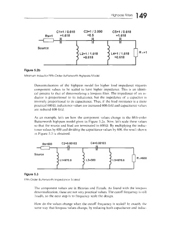
149
                                                                   Highpass Filters


                                                        II


                                                 L2=1 11.618       L4=1 11.618      R L=I


                      Denormalization  of  the  highpass  model  for  higher  load  impedance  requires
                      component  values  to  be  scaled  to  have  higher  impedance.  This  is  an  identi-
                      cal process to that of  denormalizing a lowpass filter. The impedance of  an in-
                      ductor is proportional  to its  inductance.  but  the  impedance  of  a capacitor  is
                      inversely proportional  to its capacitance. Thus, if  the load  resistance  is a more
                      practical 600R, inductance values are increased 600-fold and capacitance values
                      are reduced  600-fold.

                      .4s  an example.  let's  see hoM  the  component  \dues change  in  the  fifth-order
                      Butterworth  highpass model given in  Figure 5.2a. Now. let's scale these values
                      so that the source and load are terminated in 600Q. By  multiplying  the induc-
                      tance values by 600 and dividing the capacitance values by 600. the result shonn
                      in Figure 5.3 is obtained.

                          Rs=600      C2=0.00103       C4=0.00103


                      Source
                                                                                   R ~=600
                                     L1=970.8       L3=300          L5=970.8


                Figure 5.3
                Fifth-Order Butterworth Impedance Scaled

                      The component  values are in  Henries and Farads.  As found with  the  loivpass
                      denornialization, these are not very practical values. The cutoff frequency is still
                      1 rad/s, so the next step is to frequency scale the design.

                      How do the values change when  the cutoff  frequency is scaled!  In  exactly the
                      same way that lowpass values change, by reducing both capacitance and induc-