
Page 147 - Analog and Digital Filter Design
P. 147
1 44 Analog and Digital Filter Design
Source
IF
Load
4
R5 = 1
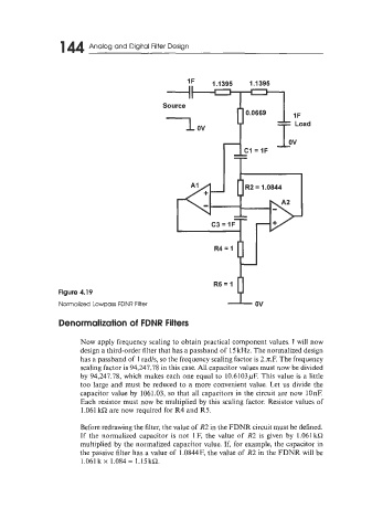
Figure 4.19
Normalized Lowpass FDNR Filter ov
Denormalization of FDNR Filters
Now apply frequency scaling to obtain practical component values. I will now
design a third-order filter that has a passband of 15 kHz. The normalized design
has a passband of 1 rad/s, so the frequency scaling factor is 2.n.F. The frequency
scaling factor is 94,247.78 in this case. All capacitor values must now be divided
by 94,247.78, which makes each one equal to 10.6103pF. This value is a little
too large and must be reduced to a more convenient value. Let us divide the
capacitor value by 1061.03, so that all capacitors in the circuit are now lOnE
Each resistor must now be multiplied by this scaling factor. Resistor values of
1.061 kR are now required for R4 and R5.
Before redrawing the filter, the value of R2 in the FDNR circuit must be defined.
If the normalized capacitor is not 1 F, the value of R2 is given by 1.061 kR
multiplied by the normalized capacitor value. If, for example, the capacitor in
the passive filter has a value of 1 .OS44 F, the value of R2 in the FDNR will be
1.061 k x 1.084 = 1.15kQ.