Page 146 - Analog and Digital Filter Design
P. 146

Analog Lowpass Filters   143


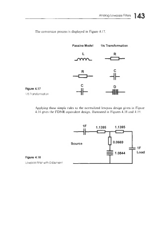
                       The conversion process is displayed in Figure 4.17.


                                             Passive Model     l/s Transformation


                                                   R                   C
                                              0


                                                   C
                 Figure 4.17
                 1 /S  Transformation


                       -4pplying these simple rules  to the normalized lowpass design given in Figure
                       4.16 gives the FDNR equivalent design. illustrated  in Figures 4.18 and -1.19.


                                                                       1.1395


                                             Source                   0.0669


                                                                  - 1.0844
                 Figure 4.18
                 Lowpass Filter with D-Element
   141   142   143   144   145   146   147   148   149   150   151