
Page 144 - Analog and Digital Filter Design
P. 144
Analog Lowpass Filters 141
Replacing the inductors and capacitors by resistors and FDNRs gives the same
low sensitivity to component tolerances. If there are two signal paths in a system
that must be closely matched in terms of amplitude and phase, an FDNR filter
is the better choice. For all these reasons there is some advantage in using the
FDNR for "all-pole" designs, such as Butterworth or Chebyshev. So now I have
convinced you. I hope. that in some application. FDNR filters are a "Good
Thing.'' But what are FDNRs?
The schematic symbol for an FDNR looks like a capacitor with four plates
instead of the usual two and is assigned a letter D. The FDNR is also kno\vn
as a D-element. A frequency dependent negative resistance (FDNR) is an
active circuit that behaves like an unusual capacitor. In a lowpass RC circuit.
the voltage drop across the shunt capacitor falls with increasing frequenc!:
Beyond the passband, doubling the frequency halves the voltage across the
capacitor. In a lowpass RD circuit, in which the FDNR has replaced the cap-
acitor. the voltage drop across the FDNR falls at double the rate. Thus. above
the passband. doubling the frequency quarters the output signal amplitude.
In decibel terms, a signal applied to an RC network has LI rate of fall of 6dB/
octave (a first-order filter). The same signal applied to an RD network has a rate
of fall of 12dB/octave of a capacitor. This double rate of fall is the reason for
the four plates in the D-element symbol, rather than the two in a capacitor
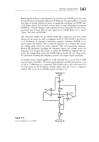
symbol. The circuit of an FDNR is given in Figure 4.15.
Terminal A
41"
Figure 4.15
Circuit Diagram of an FDNR Terminal B