
Page 145 - Analog and Digital Filter Design
P. 145
1 42 Analog and Digital Filter Design
In a simple approach where all resistors are equal to 1 R and all capacitors are
equal to 1 F, the circuit behaves like a negative resistance of -1 R. The equation
for the negative resistance is:
R2. R4.Cl .C3
D=
R5
If C1 = C3 = 1 F and R4 = R5, the negative resistance equals R2.
Now I have shown what an FDNR looks like. How do you use it? Transforma-
tion of the passive components is needed. FDNR elements are used to replace
the capacitors in passive lowpass filters. Resistors are used to replace the induc-
tors. This allows the filter size to be reduced, and a miniature hybrid circuit is
possible. The design begins with a conventional double terminated lowpass LC
filter design, in the T configuration. This has resistors (for the source and load),
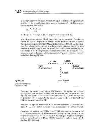
series and shunt inductors, and shunt capacitors. Figure 4.16 shows a normal-
ized elliptic lowpass LC filter.
1.1395 1 .I 395
(1 ohm source) (1 ohm load)
0.0669
Figure 4.16
Circuit of Normalized
Lowpass LC Filter
To convert the passive design into an FDNR design, the resistors are replaced
by capacitors, the inductors are replaced by resistors, and the capacitors are
replaced by FDNRs. If the source and load resistor are 1 Q, these are replaced
by capacitors of 1 E Generally, the capacitor value is 1/R, so if the load was
0.2R the capacitor would be 5 E
Inductors are replaced by resistors. A 1 H inductor becomes a 1 R resistor. Gen-
erally, R = L, so a 1.1395 H inductor would be replaced by a 1.1395 R resistor.
Capacitors are replaced by FDNRs. In an FDNR, the resistors are normalized
to 1 R and the capacitors are normalized to 1 F, to replace a 1 F capacitor. If the
normalized capacitor is not 1 F, the value of R2 (in Figure 4.15) is scaled in pro-
portion. Generally, R1 = C. Thus a 1.0844F capacitor is replaced by an FDNR
that has R2 = 1.0844R.