
Page 148 - Analog and Digital Filter Design
P. 148
145
Analog Lowpass Filters
Finally, a DC path from the source to the load must be allowed. This will give
6dB insertion loss, the same as a terminated lossless ladder filter. The output
load should be a high value, compared with the other series components: a value
of lOOkR is often used. The input capacitor must be bypassed by a resistor that
has a value less than 100 kR. The bypass resistor value should be 100 kR minus
the sum of other series resistors. Suppose the other series resistors (replacing
series inductors in the passive filter) sum to 2.416 kR, the bypass resistor should
have a value of (100 - 2.416)kR or 97.584kQ.
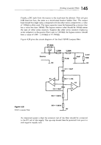
Figure 4.20 gives the circuit diagram of the final FDNR lowpass filter.
Figure 4.20
FDNR Lowpass Filter
An important point is that the common rail of the filter should be connected
to the OV rail of the supply. The op-amp should then be powered from positive
and negative supply rails.