
Page 348 - Analog and Digital Filter Design
P. 348
Filter Integrated Circuits 345
amp, the pattern of logic states can be converted into a sine wave. However, the
sine wave so produced is stepped and contains many high-frequency harnion-
ics. The answer is to lowpass filter the output to smooth these steps.
37.4k 23.2k 23.2k 37.4k
CIRCUIT A
71.5k 27.4k 22.1k 27.4k 71.5k Output
CIRCUIT B
23.2k 37.4k 37.4k 23.2k
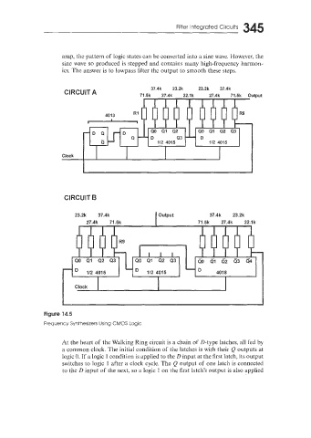
Figure 14.5
Frequency Synthesizers Using CMOS Logic
At the heart of the Walking Ring circuit is a chain of D-type latches, all fed by
a common clock. The initial condition of the latches is with their Q outputs at
logic 0. If a logic 1 condition is applied to the D input at the first latch, its output
switches to logic 1 after a clock cycle. The Q output of one latch is connected
to the D input of the next, so a logic 1 on the first latch’s output is also applied