
Page 351 - Analog and Digital Filter Design
P. 351
348 Analog and Digital Filter Design
Angle, @ degrees Amplitude, Vi
0 0
18 0.024772
36 0.095492
54 0.206 107
72 0.345492
90 0.5
108 0.654508
126 0.793893
Table 14.1 144 0.904508
162 0.975528
Output Voltage versus Phase 180 1
Angle
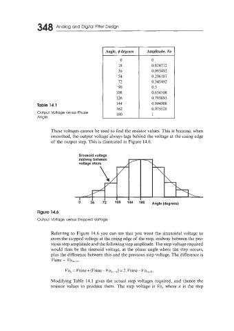
These voltages cannot be used to find the resistor values. This is because, when
smoothed, the output voltage always lags behind the voltage at the rising edge
of the output step. This is illustrated in Figure 14.6.
midway between
voltage steps \
J,”
\
/
I
Figure 14.6
Output Voltage versus Stepped Voltage
Referring to Figure 14.6 you can see that you want the sinusoidal voltage to
cross the stepped voltage at the rising edge of the step, midway between the pre-
vious step amplitude and the following step amplitude. The step voltage required
would thus be the sinusoid voltage, at the phase angle where the step occurs,
plus the difference between this and the previous step voltage. The difference is
Vsine - VO,~-,).
Modifying Table 14.1 gives the actual step voltages required, and thence the
resistor values to produce them. The step voltage is Vi, where TI is the step