
Page 354 - Analog and Digital Filter Design
P. 354
35 1
Filter Integrated Circuits
monks are very low until the clock frequency is approached, so, in theory, a
first- or second-order filter will be satisfactory.
If the clock frequency is altered, the frequency of the sine wave generator will
change. A fixed lowpass fdter will not work, so the filter’s cutoff frequency must
alter too. The solution is to use a switched capacitor filter so that as the clock
frequency increases, so does the filter’s cutoff frequency. Hence the cutoff fre-
quency is always just above the oscillator’s frequency. The frequency synthe-
sizers shown in Figure 14.5 have a clock to sine wave frequency ratio of 30: 1.
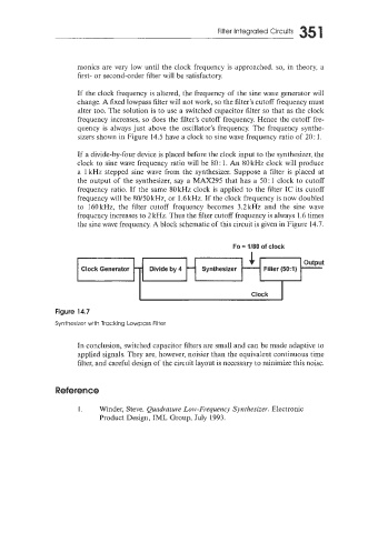
If a divide-by-four device is placed before the clock input to the synthesizer, the
clock to sine wave frequency ratio will be SO: 1. An 80kHz clock will produce
a 1 kHz stepped sine wave from the synthesizer. Suppose a filter is placed at
the output of the synthesizer, say a MAX295 that has a 50: 1 clock to cutoff
frequency ratio. If the same 80kHz clock is applied to the filter IC its cutoff
frequency will be 80/50 kHz, or 1.6 kHz. If the clock frequency is now doubled
to 160kHz, the filter cutoff frequency becomes 3.2kHz and the sine wave
frequency increases to 2 kHz. Thus the filter cutoff frequency is always 1.6 times
the sine wave frequency. A block schematic of this circuit is given in Figure 14.7.
Fo = 1/80 of clock
Clock Generator
I Clock I
Figure 14.7
Synthesizer with Tracklng Lowpass Filter
In conclusion, switched capacitor filters are small and can be made adaptive to
applied signals. They are, however, noisier than the equivalent continuous time
filter, and careful design of the circuit layout is necessary to minimize this noise.
Reference
I. Winder, Steve. Quadrature Low-Frequency Sj7~2thesiz.e~. Electronic
Product Design, IML Group, July 1993.