
Page 382 - Analog and Digital Filter Design
P. 382
Digital FIR Filter Design 379
and 4 can be added before being multiplied by A2. The signals from the output
of delay elements 1 and 5 can be added before being multiplied by Al. Finally,
the signals at the input and from the output of delay element 6 can be added
before being multiplied by AO. For the cost of three adders, multipliers A4, AS,
and A6 can be removed.
If the folded FIR filter is implemented in a digital signal processor (DSP), it
requires far less computational effort than the linear FIR filter. Summing cir-
cuits use little processor time, but multiplication requires a number of shift and
add operations. Also, reading the filter coefficients from memory takes time. The
processor is only required to read half the coefficients in a folded FIR filter.
In an FIR filter the delay to all signals is the same and does not depend upon
the signal frequency, therefore the group delay is constant. This is important for
filters handling impulsive signals because impulses contain a wide band of fre-
quencies; if the group delay is not constant, so that some frequencies are delayed
more than others, the impulse will have ringing superimposed on its waveform.
This is an undesirable distortion of the signal. On the other hand, basic speech
transmission is largely unaffected by group delay variations; for these applica-
tions IIR filters are more efficient.
The cutoff frequency (Fc) of an FIR filter is directly proportional to the data-
sampling clock frequency. Using a single set of coeffkients, the cutoff frequency
can be doubled by doubling the sampling clock frequency. The normalized clock
frequency for a digital filter is 1 Hz or 27r rads
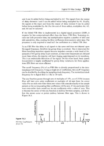
The sinc function passes through zero at multiples of UFc, so a 0.25 Hz lowpass
filter will have zero value coefficients at multiples of k4 taps from the center
value. For an odd-order filter these zero values will coincide exactly at the sample
period, so the corresponding filter coefficients will be zero. If this particular filter
were even-order there would not be any coefficients with a value of zero. This
is because the center of the sinc function is midway between samples, and there-
fore the zeroes occur at points midway between filter taps. This is shown in
Figure 16.3.
Figure 16.3
FIR Filter Coefficients
(Even N) t=O