
Page 385 - Analog and Digital Filter Design
P. 385
382 Analog and Digital Filter Design
specified. The normalized response has a sampling rate of 1 Hz (27r radians per
second), so the cutoff frequencies are relative to this (cutoff points at mc, and
me). Cutoff point mcl is the relative frequency of the lower passband edge.
Cutoff point me is the relative frequency of the upper passband edge.
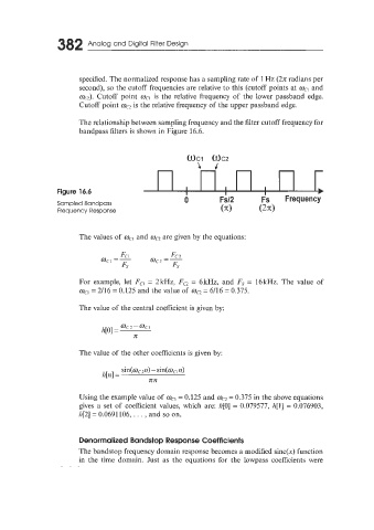
The relationship between sampling frequency and the filter cutoff frequency for
bandpass filters is shown in Figure 16.6.
- -
I I I
The values of mc, and mc2 are given by the equations:
For example, let Fcl = 2kHz, Fc2 = GkHz, and Fs = 16kHz. The value of
mcl = 2/16 = 0.125 and the value of mc2 = 6/16 = 0.375.
The value of the central coefficient is given by:
The value of the other coefficients is given by:
sin(mC2iz) - sin(mcln>
h[n] =
nn
Using the example value of mcl = 0.125 and ma = 0.375 in the above equations
gives a set of coefficient values, which are: h[O] = 0.079577, h[l] = 0.076903,
h[2] = 0.0691 106, . . . , and so on.
Denormalized Bandstop Response Coefficients
The bandstop frequency domain response becomes a modified sinc(x) function
in the time domain. Just as the equations for the lowpass coefficients were