
Page 386 - Analog and Digital Filter Design
P. 386
Digital FIR Filter Design 30
modified to give highpass coefficients. the bandpass coefficients are modified
to give bandstop coefficients. Denormalization to give a particular bandstop
response requires the lower and upper passband limits (cutoff frequencies) ea
be specified. The normalized response has a sampling rate of 1 Hz (2n radians
per second), so the cutoff frequencies are relative to this (cutoff points at coci
and wc2). Cutoff point wcl is the relative frequency of the lower stopband edge.
Cutoff point wcz is the relative frequency of the upper stopband edge.
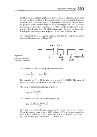
The relationship between sampling frequency and the filter cutoff frequency for
bandstop filters is shown in Figure 16.7.
OCl Oc2
Lrc
Figure 16.7
Sampled Bandstop
Frequency Response
The values of we, and wc2 are given by the equations:
For example, let Fci = 2kHz, Fez = 6kHz, and Fs = 16kHz. The value of
wcl = 2/16 = 0.125 and the value of oc- 6/16 = 0.375.
=
The value of the central coefficient is given by:
wcz -ucl
h[O] = 1 -
x
The values of the other coefficients are given by:
sin(wcin) - sin(oc2n)
Iz[n] =
nil
Note that, relative to the bandpass equations, the two sin functions are reversed.
Using the example value of we, = 0.125 and ma = 0.375 in the above equations
gives a set of coefficient values, which are: h[O] = 1 - 0.079577 = 0.920423,
h[l] = -0.076903, h[2] = -0.0691 106, . . . , and so on.