
Page 384 - Analog and Digital Filter Design
P. 384
Digital FIR Filter Design 38 1
Denormalized Highpass Response Coefficients
The highpass frequency domain response becomes a negative sinc(x) function
in the time domain. Denormalization to give a particular highpass response is
a similar process as the one just described for lowpass response denormaliza-
tion. The normalized response has a sampling rate of I Hz (2n radians per
second), so the cutoff frequency is relative to this (cutoff at wL); the value of w,
is given by the equation:
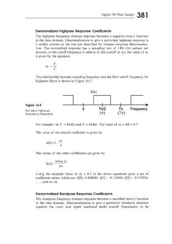
The relationship between sampling frequency and the filter cutoff frequency for
highpass filters is shown in Figure 16.5,
WC
Figure 16.5
0 Fs12 Fs Frequency
Sampled Highpass
Frequency Response (K) (W
For example, let F, = 4kHz and F, = 8 kHz. The value of w, = 418 = 0.5.
The value of the central coefficient is given by:
0
h[O] = 1 - 2
K
The values of the other coefficients are given by:
sin(w,n)
h[rz] = ~
rcn
Using the example value of w, = 0.5 in the above equations gives a set of
coefficient values, which are: h[O] = 0.840845, h[l] = -0.152606, h[2] = -0.133924.
. . . , and so on.
Denormalized Bandpass Response Coefficients
The bandpass frequency domain response becomes a modified sinc(x) function
in the time domain. Denormalization to give a particular bandpass response
requires the lower and upper passband limits (cutoff frequencies) to be