
Page 407 - Analog and Digital Filter Design
P. 407
404 Analog and Digital Filter Design
The desired filter cutoff frequency wc should be used to give a new analog cutoff
frequency wc,,fc,,,, log. The term wc represents the normalized frequency of 24Fc/Fs),
thus wc = 2n(3.4/8) = 2.6703538. When pre-warped, this becomes tan(1.335177)
= 4.1652998. In the analog transfer function, s can be replaced by 4.1652998/s,
which is the inverse of the lowpass case and gives:
1
H(s) =
17.3497221s' +5.8906235/s +1
The bilinear transform can now be carried out by substitution of Us.
Substituting for lls gives:
+ 5.8906235. { [ s]}
H(z) = 1
17.349722. {[ "'1}' Z-1 + 1
This can be simplified by multiplying everything by the highest power denomi-
nator, which is (z - 1) squared, or (z' - 2,- + 1).
The equation then becomes:
(2' - 2z + 1)
H(z) =
17.349722.(z2 + 22 + 1) +5.8906235.(z2 - 1)+ (z' -22 + 1)
Now 2-l is a single clock cycle delay, which can be achieved easily in digital
systems. The equation can be restated in terms of delays by multiplying top and
bottom by z-~, giving:
(1 - 22-1 + z-2)
H(:) =
17.349722.(1+2& +z-')+5.8906235.(1-~-')+(1-2~-~ +z')
Collecting terms on -I, z-~, and so on, to give us coefficients for each delay term,
this becomes:
(1 - 22-1 + Y2)
H(z) =
24.2403455 + 32.6994447-I + 12.45909857-'
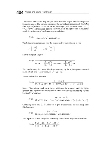
This equation can be compared to the equation for the biquad that follows: