
Page 404 - Analog and Digital Filter Design
P. 404
40 1
IIR Filter Design
transform is applied. If a highpass filter having the same cutoff frequency
were required, s would have io be replaced by 4.16529981s.
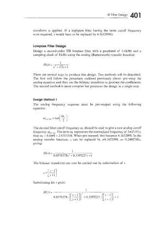
Lowpass Filter Design
Design a second-order IIR lowpass filter with a passband of 3.4kHz and a
sampling clock of 8 kHz using the analog (Butterworth) transfer function:
There are several ways to produce this design. Two methods will be described.
The first will follow the procedure outlined previously above: pre-warp the
analog equation and then use the bilinear transform to produce the coefficients.
The second method is more complex but produces the design in a single step.
Design Method 1
The analog frequency response must be pre-warped using the following
equation:
The desired filter cutoff frequency w, should be used to give a new analog cutoff
frequency w,,,,,, The term mc represents the normalized frequency of 27r(FclFs),
thus wc= 6.8~18 = 2.6703538. When pre-warped, this becomes 4.1652998. In the
analog transfer function, s can be replaced by ~14.1652998, or 0.2400788s,
giving:
1
W(s) =
0.0576378s' +0.3395227~+1
The bilinear transform can now be carried out by substitution of s.
Substituting for s gives:
1
N(z) =
0.0576378. {[ ;+fl]' + 0.3395227. {[=1]) + I
Z+l