
Page 399 - Analog and Digital Filter Design
P. 399
396 Analog and Digital Filter Design
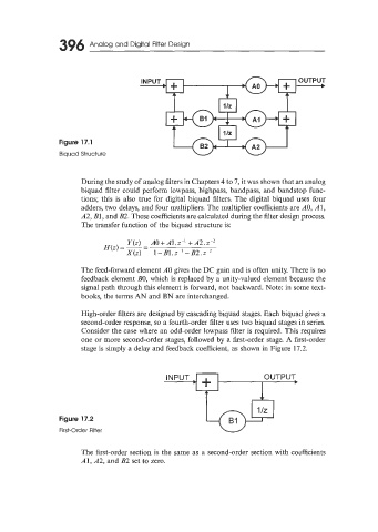
INPUT + OUTPUT
1 A0
!
I llz
Figure 17.1 1 Iz
Biquad Structure
During the study of analog filters in Chapters 4 to 7, it was shown that an analog
biquad filter could perform lowpass, highpass, bandpass, and bandstop func-
tions; this is also true for digital biquad filters. The digital biquad uses four
adders, two delays, and four multipliers. The multiplier coefficients are AO, A 1,
A2, B1, and B2. These coefficients are calculated during the filter design process.
The transfer function of the biquad structure is:
Y(z) AO+Al.z-’ +A2.z-’
H(2) = -
-
-
X(Z) 1-Bl.z-l -B2.2-*
The feed-forward element A0 gives the DC gain and is often unity. There is no
feedback element BO, which is replaced by a unity-valued element because the
signal path through this element is forward, not backward. Note: in some text-
books, the terms AN and BN are interchanged.
High-order filters are designed by cascading biquad stages. Each biquad gives a
second-order response, so a fourth-order filter uses two biquad stages in series.
Consider the case where an odd-order lowpass filter is required. This requires
one or more second-order stages, followed by a first-order stage. A first-order
stage is simply a delay and feedback coefficient, as shown in Figure 17.2.
’+ OUTPUT
INPUT
Figure 17.2
First-Order Filter
The first-order section is the same as a second-order section with coefficients
Al, A2, and B2 set to zero.