
Page 400 - Analog and Digital Filter Design
P. 400
397
liR Filter Design
Bilinear Transformation
The bilinear transform is used to convert the analog frequency response into a
digital domain response. The advantage of the bilinear transform is that any
response, be it lowpass, highpass, bandpass, or bandstop. can be converted. The
digital domain is also known as the 2-domain.
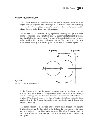
The transformation from the analog S-plane into the digital Z-plane is quite
simple to visualize. The S-plane frequency Qw) axis is wrapped around onto itself
into the Z-plane to form a circle. One side of the circle is the zero frequency
point, which is the origin on the S-plane diagram. The other side of the circle
is where the +infinity and -infinity points meet. Thls is shown in Figure 17.3.
Z-plane S-plane
Transformation O0
T
Figure 17.3
S-Plane to Z-Plane Transformation
In the §-plane, a zero on the jw axis becomes a zero on the edge of the anit
circle in the Z-plane. Poles in the S-plane should be located to the left of the jw
axis for stability; these are then transformed to be inside the unit circle of the
Z-plane. Poles in the S-plane to the right of the jw axis indicate instability in an
analog filter. In the Z-plane these poles move outside the unit circle and also
indicate instability.
The transformation of a first-order analog filter S-plane diagram into a digital
Z-plane diagram will be illustrated. In the S-plane, the pole is close to the origin
on the negative real axis. After transformation, tkis pole will appear inside the
unit circle of the Z-plane, to the left of the zero frequency point. This is shown
in Figure 17.4.