
Page 417 - Analog and Digital Filter Design
P. 417
ri
4 1 4 Analog and Digital Filter Design
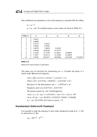
The coefficients are symmetric, so it is only necessary to calculate half the values.
a0 = a, = 1
al = a,. I, etc. To simplify matters, some values are listed in Table A.2.
1.41421
2.00000
2.61313 3.41421
3.23607 5.23607
3.86370 7.464 10 9.14162
4.49396 10.09784 14.59179
5.12583 13.13707 2 1.846 1 5 2 5.6 8 8 3 6
5.75877 16.58172 31.16344 41.98639
10 6.39245 20.43173 42.80206 64.88240 74.23343
Table A.2
Butterworth Denominator Coefficients
The phase can be calculated by substituting jw = s. Consider the phase of a
fourth-order Butterworth response.
H(s) = 1/(1+ 2.61 3 13s + 3.41421s' + 2.613 13s3 + s4)
H(w) =l/(l+j2.61313w-3.414210' - j2.613130~ +w4)
Real parts of the denominator are: 1 - 3.414210' + id.
Imaginary parts are: j2.6 1 3 1 3 w - j2.6 1 3 1 3 w3.
The phase is given by -tan-'(real/imaginary)
At w =1,n =4.-tan-'(-l.41421/0)=-tan-'(-)=-lr/2or-90".
At w =OS, 4 = -tanP[(1.0625-0.85355)/(1.306565-0.32664)]
@=-tanP[0.21323]=0.21rad/sor about -12".
Nonstandard Butterworth Passband
It is possible to scale the response to have other attenuation levels at w = 1. For
an attenuation of Kp: