
Page 53 - Analog and Digital Filter Design
P. 53
50 Analog and Digital Filter Design
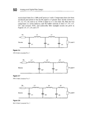
recalculated them for a 3 dB cutoff point at 1 rads. Components have also been
reordered and scaled so that for Rs equal to or greater than 1Q the network is
C1, L2, C3, L4, and so on. If Rs is equal to or is less than lR, then the first
component is a series inductor, and the ladder network is then Ll', C2', L3',
C4', and onward. Fifth- and sixth-order filter example circuits are given in
Figures 2.6, 2.1, 2.8, and 2.9.
Rs L2 L4
R Load=l
Figure 2.6
Fifth-Order Lowpass Rs t 1
Rs L1' L3' L5
Figure 2.7
Fifth-Order Lowrsass Rs s 1
Rs L2 L4 L6
Figure 2.8
Sixth-Order Lowpass Rs 2 1