
Page 54 - Analog and Digital Filter Design
P. 54
51
Time and Frequency Response
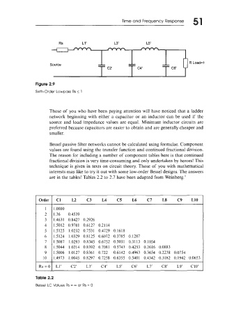
Figure 2.9
Sixth-Order Lowpass Rs 2 1
Those of you who have been paying attention will have noticed that a ladder
network beginning with either a capacitor or an inductor can be used if the
source and load impedance values are equal. Minimum inductor circuits are
preferred because capacitors are easier to obtain and are generally cheaper and
smaller.
Bessel passive filter networks cannot be calculated using formulae. Component
values are found using the transfer function and continued fractional division.
The reason for including a number of component tables here is that continued
fractional division is very time-consuming and only undertaken by heroes! This
technique is given in texts on circuit theory. Those of you with mathematical
interests may like to try it out with some low-order Bessel designs. The answers
are in the tables! Tables 2.2 to 2.7 have been adapted from Weinberg.’
Order I C1 L2 C3 L4 C5 L6 C7 LS C9 L10
1 1 .oooo
2 I .36 0.4539
3 1.463 1 0.8427 0.2926
4 1.5012 0.9781 0.6127 0.21 14
5 1.5125 1.0232 0.7531 0.4729 0.1618
6 1.5124 1.0329 0.8125 0.6072 0.3785 0.1287
7 1.5087 1.0293 0.8345 0.6752 0.5031 0.3113 0.1054
8 I. 5044 1.0214 0.8392 0.7081 0.5743 0.4253 0.2616 0.0883
9 1.5006 1.0127 0.8361 0.722 0.6142 0.4963 0.3654 0.2238 0.0754
10 1.4973 1.0045 0.8297 0.7258 0.6355 0.5401 0.4342 0.3182 0.1942 0.0653
Rs=Ol L1’ C2’ L3’ C3‘ L5’ C6‘ L7’ C8’ L9’ CIO’
Table 2.2
Bessel LC Values Rs = - or Rs = 0