
Page 49 - Analog and Digital Filter Design
P. 49
46 Analog and Digital Filter Design
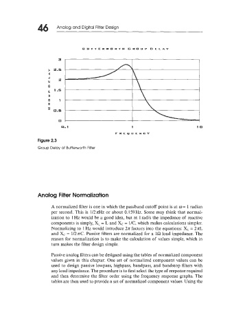
BUTTERWORTH GROUP DELAY
> 2.5
4
J
w =
0
1.5
a
0 1
p!
' 0.5
0
0.1 1 10
FREQUENCY
Figure 2.3
Group Delay of Butterworth Filter
Analog Filter Normalization
A normalized filter is one in which the passband cutoff point is at o = 1 radian
per second. This is 1127rHz or about 0.159Hz. Some may think that normal-
ization to 1 Hz would be a good idea, but at 1 rad/s the impedance of reactive
components is simply, XL = L and Xc = 1/C, which makes calculations simpler.
Normalizing to 1 Hz would introduce 2n factors into the equations: X, = 2 nL
and Xc = 1/2nC. Passive filters are normalized for a 1SZ load impedance. The
reason for normalization is to make the calculation of values simple, which in
turn makes the filter design simple.
Passive analog filters can be designed using the tables of normalized component
values given in this chapter. One set of normalized component values can be
used to design passive lowpass, highpass, bandpass, and bandstop filters with
any load impedance. The procedure is to first select the type of response required
and then determine the filter order using the frequency response graphs. The
tables are then used to provide a set of normalized component values. Using the