
Page 59 - Analog and Digital Filter Design
P. 59
56 Analog and Digital Filter Design
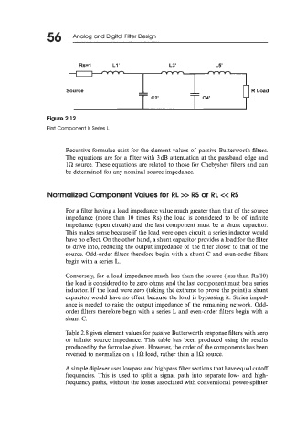
Figure 2.1 2
First Component Is Series L
Recursive formulae exist for the element values of passive Butterworth filters.
The equations are for a filter with 3dB attenuation at the passband edge and
la source. These equations are related to those for Chebyshev filters and can
be determined for any nominal source impedance.
Normalized Component Values for RL >> RS or RL cc RS
For a filter having a load impedance value much greater than that of the source
impedance (more than 10 times Rs) the load is considered to be of infinite
impedance (open circuit) and the last component must be a shunt capacitor.
This makes sense because if the load were open circuit, a series inductor would
have no effect. On the other hand, a shunt capacitor provides a load for the filter
to drive into, reducing the output impedance of the filter closer to that of the
source. Odd-order filters therefore begin with a shunt C and even-order filters
begin with a series L.
Conversely, for a load impedance much less than the source (less than Rs/lO)
the load is considered to be zero ohms, and the last component must be a series
inductor. If the load were zero (taking the extreme to prove the point) a shunt
capacitor would have no effect because the load is bypassing it. Series imped-
ance is needed to raise the output impedance of the remaining network. Odd-
order filters therefore begin with a series L and even-order filters begin with a
shunt C.
Table 2.8 gives element values for passive Butterworth response filters with zero
or infinite source impedance. This table has been produced using the results
produced by the formulae given. However, the order of the components has been
reversed to normalize on a la load, rather than a la source.
A simple diplexer uses lowpass and highpass filter sections that have equal cutoff
frequencies. This is used to split a signal path into separate low- and high-
frequency paths, without the losses associated with conventional power-splitter