
Page 61 - Analog and Digital Filter Design
P. 61
a
58 Analog and Digital Filter Design
Order1 CI L2 c3 L4 c5 L6 C7 L8 c9 L10
2.0000
1.41421 1.41421
1.00000 2.00000 1.00000
0.76537 1.84776 1.84776 0.76537
0.61803 1.61803 2.00000 1.61803 0.61803
0.51764 1.41421 1.93185 1.93185 1.41421 0.51764
0.44504 1.24698 1.80194 2.00000 1.80194 1.24698 0.44504
0.39018 1.11114 1.66294 1.96157 1.96157 1.66294 1.11114 0.39018
0.34730 I .00000 1.53209 1.87938 2.00000 1.87938 1.53209 1 .OOOOO 0.34730
IO 0.31287 0.90798 1.41421 1.78201 1.97538 1.97538 1.78201 1.41421 0.90798 0.31287
L1’ C2’ L3’ C4’ L5’ C6’ L7‘ C8’ L9’ CIO’
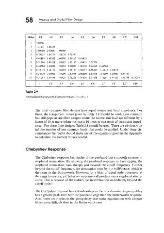
Table 2.9
Normalized Butterworth Element Values, Rs = RI = 1
The most common filter designs have equal source and load impedance. For
these, the component values given in Table 2.9 should be used. Less common
but still popular are filter designs where the source and load are different by a
factor of 10 or more (when the load is 10 times or one-tenth of the source imped-
ance). For these filter designs, Table 2.8 should be used. There are obviously an
infinite number of less common loads that could be applied. Under these cir-
cumstances the reader should make use of the equations given in the Appendix
to calculate the element values needed.
Chebyshev Response
The Chebyshev response has ripples in the passband but a smooth increase in
stopband attenuation. By allowing the passband response to have ripples, the
stopband attenuation rises sharply just beyond the cutoff frequency. Further
beyond the cutoff frequency, the attenuation rises by n x 6dB/octave, which is
the same as the Butterworth. However, for a filter of equal order measured at
the same frequency, a Chebyshev response will produce more stopband attenu-
ation. This is because of the sudden rise in attenuation immediately beyond the
cutoff point.
The Chebyshev response has a disadvantage in the time domain; its group delay
has a greater peak level near the passband edge than the Butterworth response.
Also, there are ripples in the group delay that make equalization with all-pass
filters more difficult than in the Butterworth case.