
Page 58 - Analog and Digital Filter Design
P. 58
55
Time and Frequency Response
IO0
90
80
70
60
50
40
30
20
10
0
1 10
FREQUENCY
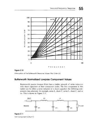
Figure 2.10
Attenuation of the Butterworth Response Values Filter Order (n)
Butterworth Normalized Lowpass Component Values
Butterworth passive lowpass filters have a ladder network of series inductors
with shunt capacitors at their connection nodes. The first component in this
ladder can be either a series inductor or a shunt capacitor; the following com-
ponents then alternate: for example, series L, shunt C, series L, shunt C, and so
on. This is shown in Figure 2.1 1.
Figure 2.1 1
First Component Is Shunt C