
Page 77 - Analog and Digital Filter Design
P. 77
74 Analog and Digital Filter Design
L2 L4
L6
c2 c4
Input II II output
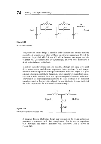
Figure 2.23
Sixth-Order LowDass
The pattern of circuit design as the filter order increases can be seen from the
examples. A seventh-order filter will have an extra two capacitors; C6 will be
connected in parallel with L6, and C7 will be between the output and the
common rail. Odd-order filters are symmetrical, but even-order filters have a
single series inductor to the load.
Minimum capacitor designs are also possible, although less likely to be used
since inductors are much harder to produce than capacitors. In this design,
inductors replace capacitors and capacitors replace inductors; Figure 2.24 gives
a circuit schematic example. In this design, series inductors replace shunt capac-
itors, and a series resonant shunt arm replaces the parallel resonant series arm.
The value of the shunt capacitor is equal to the series inductor in the minimum
inductance design. Similarly, the value of the shunt inductor is equal to that of
the series capacitor in the minimum inductance design.
L1 L3
I
Input i output
L2
1
Figure 2.24
T c2
Minimum Capacitor Lowpass Filter I
A highpass Inverse Chebyshev design can be produced by replacing lowpass
prototype components with their complement; that is, replace capacitors
with inductors and replace inductors with capacitors. This is shown in
Figure 2.25.